Introducing Poliigon for Sketchup Pro

Poliigon is pleased to announce support for Sketchup Pro and rendering with Vray.

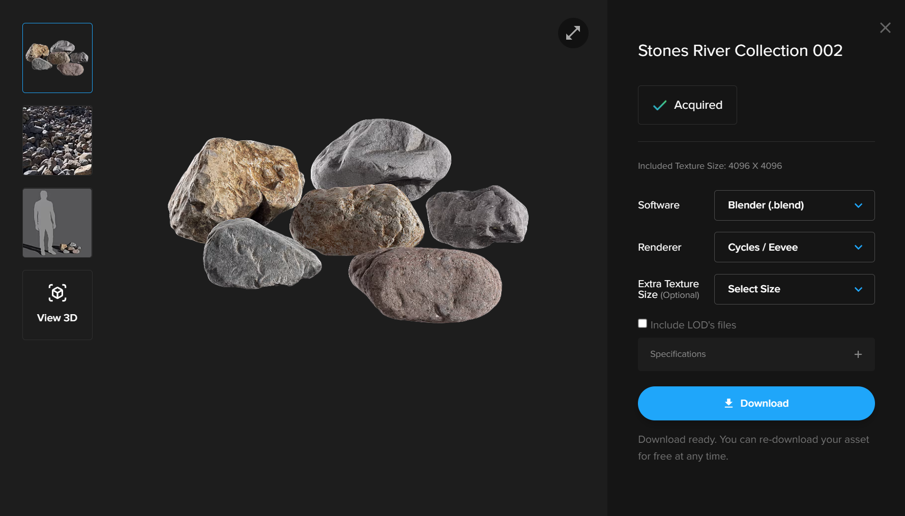
Use the new Sketchup Extension to automatically create photorealistic materials, and import the new .skp models.

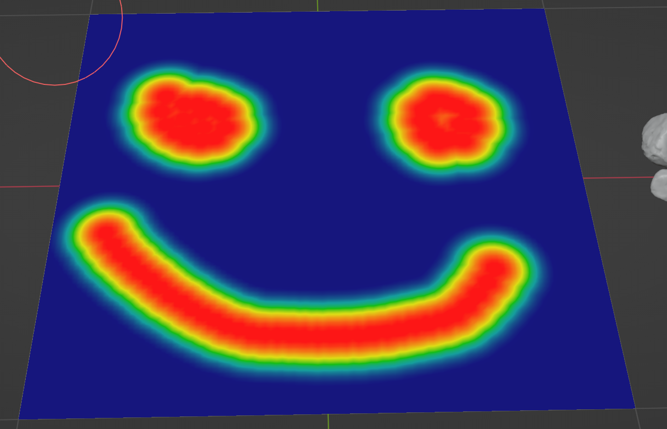
Instant Texture Importing

Gone are the days of needing to import texture maps one by one. Simply click the Poliigon Extension, select any one single texture map and the Poliigon Extension will import all the associated textures and instantly create a Vray material.

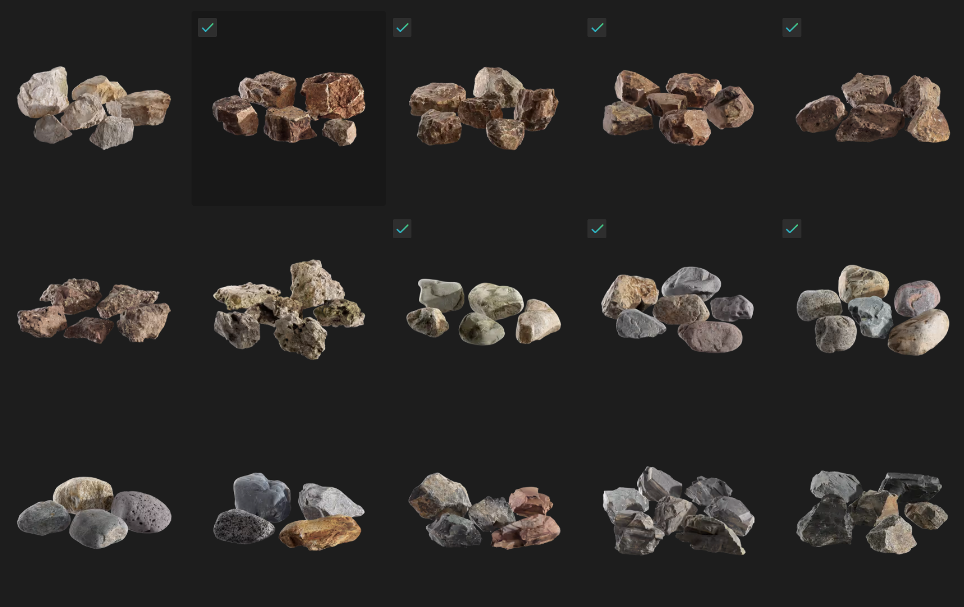
Instant Model Importing

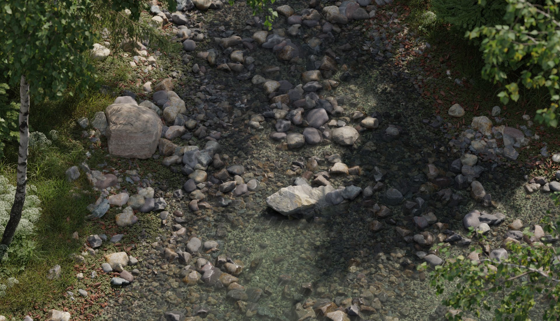
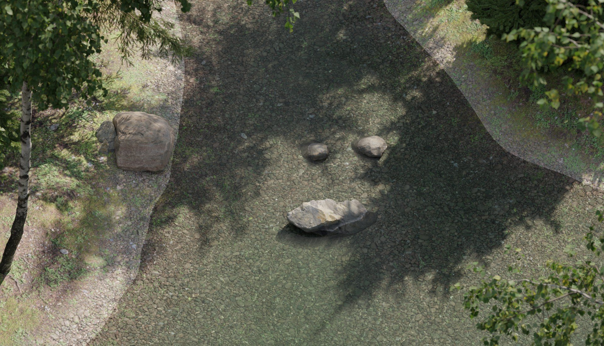
Photorealistic 3D models are often too high-poly to import into SketchUp, which will either grind to a halt or flat out crash. So after talking with SketchUp users, we came up with a solution to this that is both lightweight to the viewport & photoreal at rendertime.

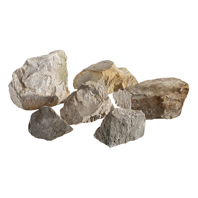
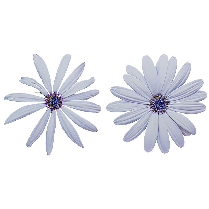
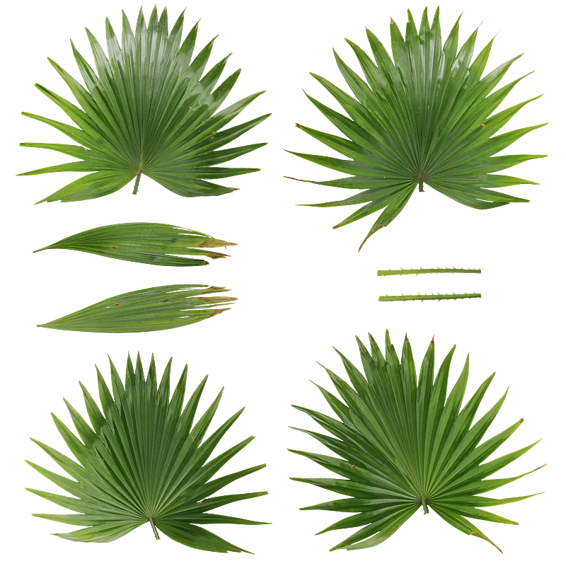
Left: The Proxy, Right: The model at rendertime.

The solution is our Poliigon Sketchup extension, which will import the skp (a low-poly proxy mesh used just for the viewport) but then swap it out for a V-Ray mesh (.vrmesh) at rendertime.

Additionally, you’ll be pleased to discover that objects with sub-parts can be individually moved.

While this initial launch is for rendering with Vray only, if you have another render engine you’d like supported, fill out this quick survey to let us know.

Environment Scattering in Blender

If you're making an environment, you'll need to scatter lots of objects. Previously, the way to do this was with particles - but the better, more flexible method in Blender 3.0 and above is to use the new Geometry Node feature. 

In this article, you’ll learn how to set up a simple Geometry Node system to scatter objects and do some customizations most common for environments, like randomizing rotation, scale, and weight painting.

What you’ll need to follow along:

  • A plane to scatter onto. We’ll be using a simple plane, but in your scene, it may be your ground surface or whatever object you want to scatter objects onto.

  • Something to scatter! We’ll be using a selection of rocks from Poliigon.com

Design along with us by watching the video above, or slow it down with the written version below. 


1. Select a Target Object

Select whatever object you want to scatter objects on to - in this example, we’re using a simple plane primitive.

2. Set up a fresh set of Geometry Nodes

Jump over to the Geometry Nodes tab, something that was added to Blender in version 3.0. 

From there, you can click on the NEW button to create a new set of geometry nodes. It will also add a geometry node modifier to your target object automatically.

Next add these nodes:

There’s almost unlimited potential for what you can create and do using geometry nodes, but these three nodes will be used time and time again. Here’s what they do in more detail:

Distribute Points on Faces

This node creates a random series of points covering the faces of the target object. There are a whole bunch of settings to play with, but we’ll explore those in more detail once we have the basic scattering setup in place.


Instance on Points

This node is used to add instances of geometry onto the points created by the Distribute Points on Faces node. There are controls for rotation and scale, as well as some other more advanced options that will not be covered in this article.


Join Geometry

This node does exactly what it says - it joins two separate parts of our node group together. In this example, we’ll be using it to display our original target object as well as the scattering objects we add.

The above setup gives us everything we need to get scattering! We have a:

  • Distribute Points on Faces node to randomly create points over our object.

  • Instance on Points node to use those points for distributing instances of our scatter objects.

  • Join Geometry node so we can see both our scatter objects and our original plane.

3. Adding in Scatter Objects

We need some objects to scatter onto our target object. In this example, we’ll be using the Stones River Collection 002 from Poliigon, though for an actual scene you’d want more variation than this by creating multiple systems for different scattering groups. 

Thankfully, Poliigon has a whole host of options - you can download a few here if you want to follow along.

Once you have the scatter objects you want downloaded, append them into Blender either by dropping the .blend onto your viewport, or by using the File > Append menu.

Whatever objects you pick, make sure they are all assigned to the same Collection.

Finally, we need to be able to reference this collection of scatter objects within our Geometry Nodes. You can do this by dragging the collection from the overview into your node panel. This will automatically create a pre-setup Collection Info node

Alternatively, you can just add in a Collection Info node and manually select the appropriate collection.

All that’s left is to connect the output of the Collection Info node into the Instance input on the Instance on Points node.

Also be sure to mark the Separate Children, Reset Children, and Pick Instance checkboxes. This will make sure that each scatter object is treated as an individual and that none of its current position or rotation is used.

If you’ve followed along correctly, you should see something like this:


4. Adding Rotation and Scale Controls

We’re getting there, but we need more control over the scattering. We’re going to use a node found in the Utilities category called Random Value. This allows us to generate a random value for each point in our setup.

For rotation, change the first Random Value node to a Vector using the dropdown. Then, connect the output to the Rotation input on our Instance on Points node.

Leave all the min values at 0.

For the max values, use:

  • 0 for X

  • 0 for Y

  • For Z, type in “tau” or 6.283 (which is Pi times 2) - because the value is in radians, this will give us a total max rotation of 360 degrees for our scatter objects.

For scale, leave the second Random Value node as a float value, which is its default. Connect it directly to the Scale input of the Instance on Points node. Yes, this will mean connecting a gray Float output to a purple Vector input, but it’s nothing to worry about - it’ll just mean that each of the X,Y, and Z values of the vector will reference the same float value, which is exactly what we’d want to ensure our scatter objects maintain their shape and aren’t distorted along any axis.

For the Min Scale Value, we’ll use 0.7 as we don’t want too much variation. We can leave the Max Value on its default of 1. Be careful to never use a Min Value of 0 here as, you won’t see objects that are a 0 scale, but they will still be calculated, which will slow down your render and increase resource usage.

This should be the result, if followed correctly:

5. The Distribute Points on Faces node

I mentioned earlier we’d be taking a look at this node in more detail. Now is that time!

The type by default is set to random - which isn’t really ideal for scattering. Instead, change this to Poisson Disk - this creates some additional controls that we’ll be making heavy use of.

The first one we want to adjust is the Density Max value. As you increase this value, you’ll see more and more scattered objects. A good technique here is to keep increasing the number until most of your surface is covered with objects. You’ll notice that a lot of them will be clipping inside its neighbor - this is something we’ll address next.

For the Distance Min value, we want to use a value of around 0.03m, though it’ll vary depending on the scattered object. Basically, it’ll mean that any two objects that are closer than the desired amount will have one of the objects omitted.

It’s a balancing act between these two values to get the right result. You’ll always have some clipping in most cases, but you should be able to effectively minimize it.

The final value we want to look at here is the Density Factor. This is essentially a multiplier for the Density Max value. A value of 0.5 here would give us half the total amount, for example.

What use is this, you ask? Well, notice how it has a little diamond input rather than the normal circular blob? This indicates that a per-point value can be used here - i.e. we can use a texture, a weight paint, or a more per-point node calculation. It’s the Weight Paint we’re interested in, so for now, connect the Density Factor to a new group input.


6. Using a Weight Paint to control Distribution

Before we can paint our weight paint, we need to make sure the object has plenty of geometry to paint on, because a weight paint is just assigning values to a vertice. In this example, I’m just going to subdivide my plane by pressing the RMB on our object in Edit Mode, selecting Subdivide, and then entering in 100 as the number of cuts.

With that done, just jump over to the Weight Paint tool and paint in where you would like the scatter objects to go. 

While we are using a weight paint in this example, a painted texture would work just as well and use the exact same method. 

An optional but advised step here is to name the newly created vertex group. I’ve called mine ‘Rocks’.

All that’s left now is to send the information within this vertex group to the Density Factor input in our geometry node setup - this is why we created a new group input for it. This is now listed in the Geometry Nodes modifier and all we have to do is assign our vertex group to that input. In my case, that meant selecting the Rocks vertex group.

7. Scatter away!

And that, as they say, is that - we have our quick, simple scattering setup that you can replicate over and over for all the various scattering groups you might need in your scene - grass clumps, flowers, plants, rocks, debris, pretty much anything you could think of.

Happy scattering, folks!